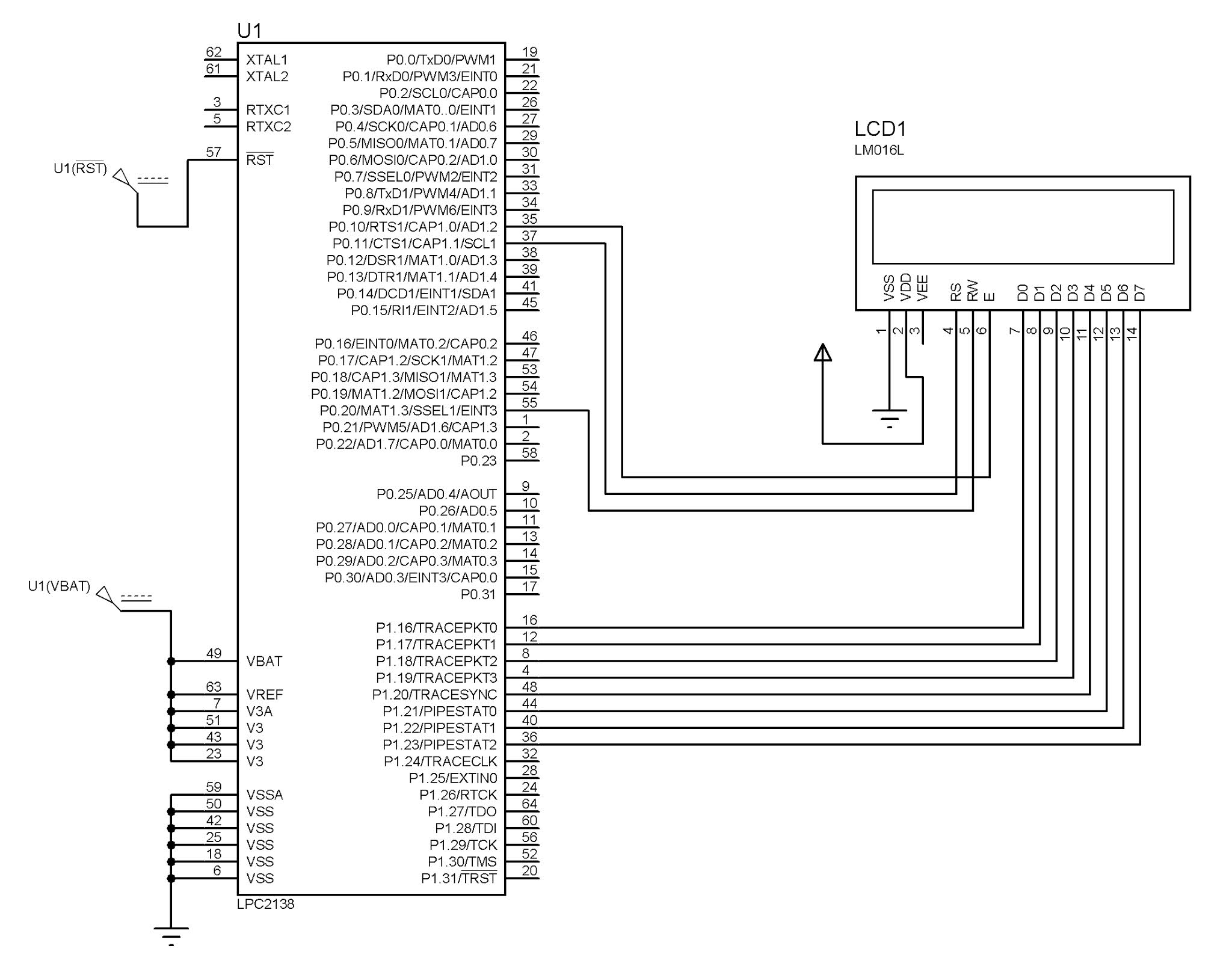
Circuit Diagram:
// Code for 16x2 interfacing with ARM7:
#include<lpc214x.h>
#define LCD_PORT 0x00FF0000
#define EN 1<<10 //define RS pin
#define RS 1<<11 //define EN pin
#define RW 1<<20 //define RW pin
#define LCD_SHIFT 16 //shift data by LCD_SHIFT bits
void LCD_init(void);
void LCD_data(unsigned char);
void LCD_cmd(unsigned char);
void LCD_display(int, int, char*);
void lcd_delay(unsigned int time)
{
int i,j;
for(i=0;i<time;i++)
for(j=0;j<200;j++);
}
void LCD_data(unsigned char ch) //function to send data
{
IOCLR1 = LCD_PORT; //clear LCD pins
IOSET1 = ch<<LCD_SHIFT; //shift data and set only the data bits
IOSET0 = RS; //RS =1
IOCLR0 = RW; //RW = 0
IOSET0 = EN;
lcd_delay(100);
IOCLR0 = EN; //EN pulse
}
void LCD_cmd(unsigned char ch) //function to send command
{
IOCLR1 = LCD_PORT;
IOSET1 = ch<<LCD_SHIFT;
IOCLR0 = RS; //RS = 0
IOCLR0 = RW; //RW = 0
IOSET0 = EN;
lcd_delay(100);
IOCLR0 = EN; //EN pulse
}
void LCD_init(void)
{
PINSEL0 &= 0xFF0FFFFF; //Pins P0.10 and P0.11 as GPIO
PINSEL1 &= 0xFFFFFCFF; //Pin P0.20 as GPIO
PINSEL2 &= 0xFFFFFFF3; //PORT1 as GPIO
IODIR0 = RS | EN | RW; //set the pins as output
IODIR1 = LCD_PORT;
LCD_cmd(0x38); //8bit use both lines
LCD_cmd(0x06); //Entry mode
LCD_cmd(0x0C); //display ON cursor OFF
LCD_cmd(0x01); //Clear display
LCD_cmd(0x80); //cursor at 1st line 1st position
}
void LCD_display(int row, int pos, char *ch)
{
unsigned char temp;
if(row==1)
{
temp = 0x80 | (pos-1); //set cursor at 1st line pos position
}
else
{
temp = 0xc0 | (pos-1); //set cursor at 2nd line pos position
}
LCD_cmd(temp);
while(*ch) //while data is valid, display the string
LCD_data(*ch++);
}
void delay(unsigned int time)
{
unsigned int i,j;
for(i=0;i<time;i++)
for(j=0;j<5000;j++);
}
int main()
{
unsigned int temp;
LCD_init();
while(1)
{ LCD_display(1,4,"entc dept");
LCD_display(2,4,"pccoe pune"); //display buffer
delay(20);
}
}
Comments
Post a Comment